Five-axis machining has changed what manufacturers can make, how fast they can make it, and how many setups they can eliminate. But it hasn’t changed physics. You can own a world-class machine, generate a perfect toolpath, and use premium tooling — and still miss tolerance because your workholding system wasn’t stable or repeatable enough to support multi-axis cutting.
In fact, as machines get better, fixture error becomes a bigger share of total process error. The machine can hit its commanded position within microns. The CAM can generate smooth, collision-free motion. The tooling can survive aggressive parameters. If parts are still out of spec, the remaining culprit is usually upstream: alignment drift, clamping distortion, interface repeatability, or operator variability.
This article is a practical blueprint for five-axis workholding that actually holds up in production, not just in a demo cut. We’ll break down the key failure modes, explain why five-axis magnifies them, and outline a system approach to make your accuracy reliable over weeks and months — even with high-mix workflows.
Why five-axis amplifies workholding problems
In a three-axis machine, the tool typically approaches the workpiece from a single direction, mostly normal to the table surface. Gravity is constant. The lever arms are predictable. If your fixturing is “good enough,” you can often get away with it.
Five-axis changes that. The tool attacks the workpiece from multiple directions, often with steep tilts, long gauge lengths, and changing gravity vectors. That introduces new sensitivity:
- A tiny base shift becomes a larger positional error when the tool is extended at a tilt.
- Cutting loads can pull the part differently as the rotary axes move.
- The part may “settle” microscopically after a rotation, especially if clamping is uneven.
- Clearance requirements force taller fixtures, which increases leverage and magnifies small interface errors.
So five-axis isn’t just “three-axis plus two rotations.” It’s a different mechanical environment that punishes weak or inconsistent workholding.
The three layers of five-axis workholding
The easiest way to think about five-axis fixturing is in layers. Each layer must be correct for the final system to be accurate.
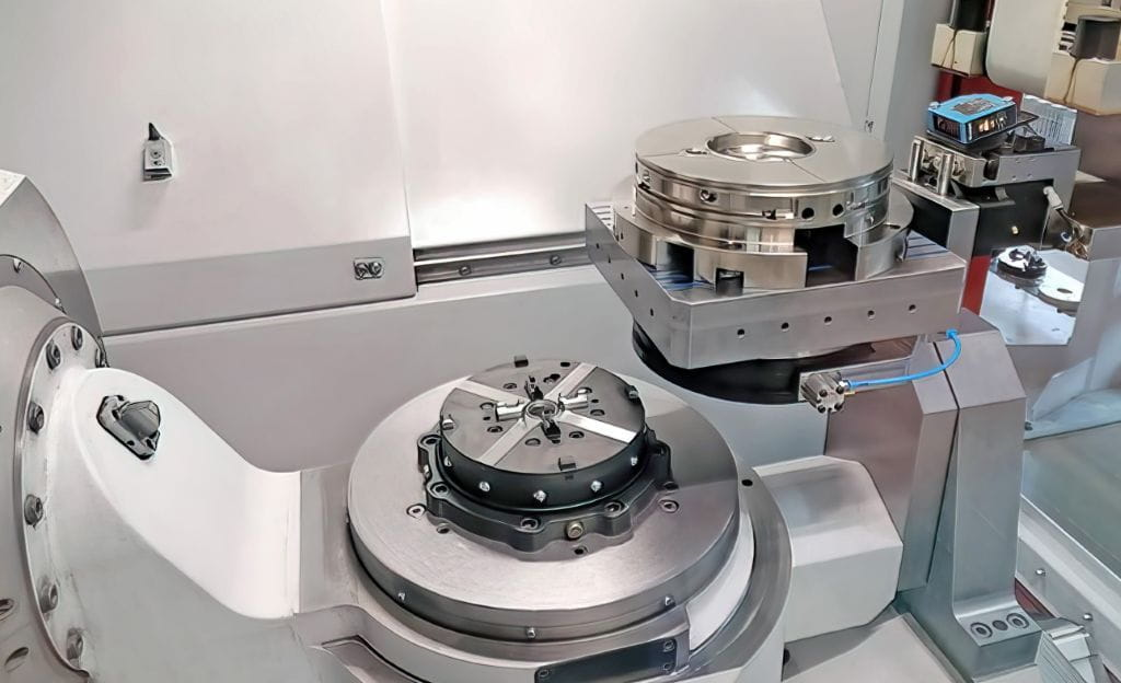
- Machine-to-fixture interface
How your fixture/pallet attaches to the rotary table or trunnion. - Fixture body / riser / pallet structure
The structure that provides stiffness and clearance. - Part clamping method
How the part is held, how it deforms, and how repeatable its location is.
Most accuracy issues happen because one of these layers is treated casually while the others are optimized. Five-axis doesn’t allow that. Weakness in any layer becomes a tolerance hit.
Layer 1: your interface is your datum
If the interface between the machine and fixture isn’t repeatable, every other improvement is wasted. Traditional five-axis setups often rely on T-slots, bolts, and manual indicating. That can work, but it introduces operator variability and always demands re-verification after removal.
In five-axis production, the true goal is detach and reattach without re-indicating. That means:
- You can pull a fixture off to inspect a workpiece.
- You can return later to finish another batch.
- You can move the same pallet to another compatible machine.
- Your work offset follows the fixture instead of being rebuilt by hand.
A repeatable quick-change baseline is the most direct way to get there. It defines a mechanical “home” for fixtures with high positional repeatability, so the datum doesn’t reinvent itself each time. Some shops standardize this layer using modular zero-point families such as 3r systems, which let fixtures behave like calibrated modules rather than custom one-offs that need fresh indicating at every swap.
The payoff is not just speed. It’s the removal of uncertainty. When the interface is repeatable, your five-axis machine stops being a “setup art project” and starts acting like a consistent production tool.
Clearance is as important as precision
Five-axis machining is only as good as your access. If your fixture blocks tool reach, rotary travel, or probing lines of sight, your programs get compromised. That’s why five-axis fixtures are often taller than their three-axis equivalents.
But taller fixtures mean higher leverage. Even small errors at the base interface produce bigger angular errors at the workpiece. The solution is a balance:
- A repeatable interface so height doesn’t force re-indicating.
- A stiff structure so height doesn’t flex.
- A clamping method that does not shift when gravity vectors change.
Which leads to the second layer.
Layer 2: stiffness, symmetry, and load paths
Once the interface is solid, the next threat is fixture body deformation. In five-axis, your fixture is not only resisting cutting loads — it’s resisting loads through many orientations.
Key design principles:
- Keep overhangs short.
Every extra millimeter of overhang is leverage you must defeat with stiffness. - Use thick, ribbed sections rather than thin plates.
Thin plates are springboards that vibrate and warp under torque. - Drive bolts into deep, rigid bosses.
Surface-level fastening allows micro-rocking. - Favor symmetric geometries.
As the table rotates, gravity shouldn’t bias the fixture into a new settled posture. - Control joint stackups.
Riser to base, base to receiver, receiver to machine — each joint adds error potential.
A quick diagnostic: if you can tap your fixture body with a mallet and see visible deflection or hear a “ringing” resonance, that structure is likely too compliant for full-tilt five-axis finishing.